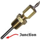
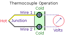
Thermocouple Input Circuitry
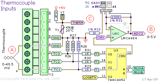
The image shows a small part of the 2Y controller schematic.
Similar circuitry is used in other controllers that offer thermocouple capability
although the 3B1 controller, the 3H1
(and the 2B0 too)
have additional differential input stages designed to improve accuracy and noise rejection.
Refer to the (A) section (red circle, left side). This shows a thermocouple connected to the TC1 input.
The thermocouple's + end goes to a 1kΩ resistor (R29)
and then to multiplexer (74HC4052 mux U3).
The multiplexer takes one of four inputs (T1, T2, T3 or LOGBTN) and, depending on the state of signals MUXA and MUXB,
shunts one of these input voltages to the output pin CMX.
The dotted line shows the signal path from T1-X2-CMX
IC U8C is one section of a quad rail-to-rail op-amp (LMC6484).
This op-amp is wired as a basic non-inverting amplifier with gain determined by the two feedback resistors R32 and R33.
The jumper J1 shorts R32 and effectively changes it from a 100kΩ to a 0k resistor.
The amp's gain is (referring to op-amp theory):
       Jumper in x101 position
V(out) = V(in) * (R32 + R33) / R33
       = V(in) * (1 + 100) / 1
       = V(in) * 101
|
       Jumper in x1 position
V(out) = with J1 shorting R32 so R32 = 0
       = V(in) * (1 + 0) / 1
       = V(in) * 1
|
The op-amp's output goes to a pin of the CPU which is set up to convert a 0 to 5 Volt signal voltage to a 10 bit count (0 to 1023).
Refer to the (B) section where, for a full 5 Volt signal, the input signal must be 5/101 = 49.505 mVolts.
This voltage corresponds to an uncorrected K-type thermocouple temperature of 1218°C.
A count of 1023 therefore corresponds to 1220 degrees.
The maximum resolution the circuitry is therefore 1220/1023 which is approximately 1.2 degrees per count.
In practice there are sources of error such as noise, op-amp and ADC non-linearity, etc. and one can expect
a corrected resolution of perhaps 5°C.
This 5°C resolution suggests that K-type thermocouples should not be used to measured room temperatures or
even the lower temperatures found in an engine bay (other type thermocouples may be more aapropriate).
K-type thermocouples are however ideal for exhaust gas temperature measurements close to the exhaust valve.
Note also that the temperature the thermocouple measures depends very much on the position within the exhaust stream
and some variations between exhausts, that are otherwise flowing the same gas temperature, can be expected.
EGT measurement is a good way to see short term variations between cylinders when the overall fuel trim has not changed.
The (C) section of this circuit is used to measure the temperature of thermistor T1.
This, and cold-junction compensation, is described in a section below.
Thermocouple Voltage to Temperature Conversion
The relationship between thermocouple voltage and temperature is not linear.
This k-type table shows the relationship over the range of 0 to 1370°C
(it is derived from NIST data).
The count is a 10 bit ADC count after the thermocouple voltage is amplified by 101 and converted (1023 represents 5.0 Volts).
If you graph these values between 0 and 1200°C the graph looks like a straight line
but a straight-line approximation, using the 0 and 1220°C entries as the end-points,
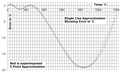
can result in up to 19°C error.
The image at right shows the two-point linear-interpolation
error plotted against temperature
(it's harder to see this error when the real and calculated temperates are plotted directly).
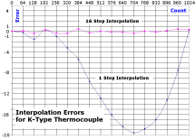
The four red straight lines on the graph (to the right) show a possible solution to this problem -
break the conversion into four different sections and treat each as a separate linear conversion.
In practise, it is more convenient to divide the thermocouples count interval into a larger number of equal width intervals.
For example, to cover the interval 0 to 1023, we could use 16 intervals each covering a count of 64.
To describe the resulting 16 straight line segments we must use a 17 point table.
This is shown at left.
The following form and associated JavaScript code show how the 17 point table
is used to linearly interpolate a supplied count value.
JavaScript 16-Interval (17-Point) Table & Interpolation Code
| |
|
Thermistor and Cold Junction Compensation (CJC)
A thermistor
is a resistor whose value varies with absolute temperature.
Note that a thermistor is quite unlike a thermocouple (which produces a voltage depening on temperature difference).
The (C) section of the circuit above measures the temperature of thermistor T1.
T1 is close to the thermocouple connector and is designed for use with cold-junction compensation (CJC).
As a thermocouple measures the difference in temperature between the hot and cold junctions,
we must know the cold junction's temperature to calculate the temperature of the hot junction.

We add thermistor T1's temperature to the thermocouple temperature to calculate actual thermocouple junction temperature.
Referring to the schematic above, the THERM signal is generated
by a voltage divider made up of a fixed 47kΩ resistor in series with T1 (whose nominal resistance is 47kΩ at 25°C.
As negligible current flows through the THERM input to the measuring circuit,
the same current i flows through the 47kΩ resistor and the thermistor with resistance R.
Using Ohms Law (V = i * R)
we can develop two equations (note that current is in mA and resistance in kΩ)
V is the THERM voltage:
       5.0 = i * (47 + R)                      V = i * R
         i = 5.0 / (47 + R)                    i = V / R
         V = 5.0 * R / (47 + R)
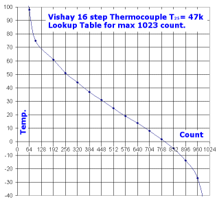
The image at right
shows the relationship between THERM ADC count and thermistor temperature.
This eXcel spreadsheet describes the process involved in developing the
16-segment count to temperature lookup table.
The previous Javascript code can be used with the following table (this is also a °C table):
var ThermistorTemp =
 [161, 98, 75, 61, 51, 44, 37, 31, 25, 19, 14, 8, 2, -5, -14, -27, -63]
Data Frame Analogue & Thermocouple Fields
A potential problem exists in interpreting the values from the logging data frame.
The thermocouple and thermistor fields are defined with a maximum count of 1023 (10 bits).
The analogue data fields, although using the same hardware, are defined with a maximum count of 8191 (13 bits).
On some models it's possible to configure the hardware to use an analogue channel to be a thermocouple channel.
This means that analogue inputs that are used as thermocouple inputs must be scaled (÷ 8) before going through the
lookup table routine.
|
